Wire sizing step by step, on one circuit →
Wire gauge chart
AWG and kcmil sizes with diameter, area in mm², circular mils and resistance. Every figure on this page is calculated from the gauge formula, not copied from a table.
The calculation sheet
Where these numbers come from
AWG is a geometric series with two fixed points. 36 AWG is 0.005 inch across, and 0000 AWG, written 4/0, is 0.46 inch. Between them are 39 steps, each the same ratio apart:
Here n is the gauge number, with n = 0, −1, −2, −3 for 1/0 to 4/0. The area is π/4 × d². A circular mil is the area of a circle one thousandth of an inch across, so the circular mils are the diameter in mils, squared.
That’s why the whole table below can be calculated, and none of it comes from anyone’s copyrighted table. Sizes above 4/0 aren’t part of the gauge series. They’re named by area in thousands of circular mils, which is what kcmil means.
Why bigger numbers mean thinner wire
The gauge number roughly counts how many times the wire was drawn through a smaller die. More passes, thinner wire: 24 AWG is thin, 2 AWG isn’t. The numbers run out below one pass, so the big sizes are written 1/0, 2/0, 3/0 and 4/0.
Two rules of thumb come from the ratio: every 3 gauge numbers doubles or halves the area, and every 10 changes it about tenfold.
AWG and mm² don’t mix
The nearest metric column is only a rough guide. 4 AWG is 21.15 mm². That’s close to 25 mm² but not the same, and you can’t order 25 mm² from a North American supplier anyway. Swapping one for the other without noticing is how errors get into a design, so this site keeps the two apart. The nearest size in the other system is shown only as a note, with the difference in per cent.
The resistance columns
The resistance in the table is for a solid conductor at 20 °C, worked out as ρ/A from the resistivity of the metal: 1.7241 × 10⁻⁸ Ω·m for annealed copper at 100 % IACS, 2.8264 × 10⁻⁸ for aluminium at 61 %. In practice two things change it, and the calculator above handles both:
- Stranding. The strands spiral, so they’re longer than the cable. The usual allowance is about 2 %, so the calculator uses 1.02 by default.
- Temperature. Copper resistance goes up about 0.39 % per degree. At 75 °C it’s about 22 % higher than at 20 °C, which is why a voltage drop worked out at room temperature comes out too low.
If you need the drop along a run, use the voltage drop calculator.
AWG and kcmil
Diameter, area, circular mils and the resistance of a solid conductor at 20 °C, calculated from the formula above.
| Size | Diameter mm | Diameter in | Area mm² | Circular mils | Copper Ω/km | Copper Ω/1000 ft | Aluminium Ω/km | Nearest metric |
|---|---|---|---|---|---|---|---|---|
| 36 AWG | 0.127 | 0.005 | 0.01267 | 25 | 1361 | 414.8 | 2231 | 0.5 mm² -97% |
| 35 AWG | 0.1426 | 0.005615 | 0.01597 | 32 | 1079 | 329 | 1769 | 0.5 mm² -97% |
| 34 AWG | 0.1601 | 0.006305 | 0.02014 | 40 | 856 | 260.9 | 1403 | 0.5 mm² -96% |
| 33 AWG | 0.1798 | 0.00708 | 0.0254 | 50 | 678.8 | 206.9 | 1113 | 0.5 mm² -95% |
| 32 AWG | 0.2019 | 0.00795 | 0.03203 | 63 | 538.3 | 164.1 | 882.5 | 0.5 mm² -94% |
| 31 AWG | 0.2268 | 0.008928 | 0.04039 | 80 | 426.9 | 130.1 | 699.8 | 0.5 mm² -92% |
| 30 AWG | 0.2546 | 0.01003 | 0.05093 | 101 | 338.5 | 103.2 | 555 | 0.5 mm² -90% |
| 29 AWG | 0.2859 | 0.01126 | 0.06422 | 127 | 268.5 | 81.83 | 440.1 | 0.5 mm² -87% |
| 28 AWG | 0.3211 | 0.01264 | 0.08098 | 160 | 212.9 | 64.9 | 349 | 0.5 mm² -84% |
| 27 AWG | 0.3606 | 0.0142 | 0.1021 | 202 | 168.9 | 51.47 | 276.8 | 0.5 mm² -80% |
| 26 AWG | 0.4049 | 0.01594 | 0.1288 | 254 | 133.9 | 40.81 | 219.5 | 0.5 mm² -74% |
| 25 AWG | 0.4547 | 0.0179 | 0.1624 | 320 | 106.2 | 32.37 | 174.1 | 0.5 mm² -68% |
| 24 AWG | 0.5106 | 0.0201 | 0.2047 | 404 | 84.21 | 25.67 | 138.1 | 0.5 mm² -59% |
| 23 AWG | 0.5733 | 0.02257 | 0.2582 | 509 | 66.78 | 20.36 | 109.5 | 0.5 mm² -48% |
| 22 AWG | 0.6438 | 0.02535 | 0.3255 | 642 | 52.96 | 16.14 | 86.82 | 0.5 mm² -35% |
| 21 AWG | 0.7229 | 0.02846 | 0.4105 | 810 | 42 | 12.8 | 68.85 | 0.5 mm² -18% |
| 20 AWG | 0.8118 | 0.03196 | 0.5176 | 1,022 | 33.31 | 10.15 | 54.6 | 0.5 mm² +4% |
| 19 AWG | 0.9116 | 0.03589 | 0.6527 | 1,288 | 26.41 | 8.051 | 43.3 | 0.75 mm² -13% |
| 18 AWG | 1.024 | 0.0403 | 0.823 | 1,624 | 20.95 | 6.385 | 34.34 | 0.75 mm² +10% |
| 17 AWG | 1.15 | 0.04526 | 1.038 | 2,048 | 16.61 | 5.063 | 27.23 | 1 mm² +4% |
| 16 AWG | 1.291 | 0.05082 | 1.309 | 2,583 | 13.17 | 4.015 | 21.6 | 1.5 mm² -13% |
| 15 AWG | 1.45 | 0.05707 | 1.65 | 3,257 | 10.45 | 3.184 | 17.13 | 1.5 mm² +10% |
| 14 AWG | 1.628 | 0.06408 | 2.081 | 4,107 | 8.285 | 2.525 | 13.58 | 2.5 mm² -17% |
| 13 AWG | 1.828 | 0.07196 | 2.624 | 5,178 | 6.571 | 2.003 | 10.77 | 2.5 mm² +5% |
| 12 AWG | 2.053 | 0.08081 | 3.309 | 6,530 | 5.211 | 1.588 | 8.542 | 4 mm² -17% |
| 11 AWG | 2.305 | 0.09074 | 4.172 | 8,234 | 4.132 | 1.26 | 6.774 | 4 mm² +4% |
| 10 AWG | 2.588 | 0.1019 | 5.261 | 10,383 | 3.277 | 0.9988 | 5.372 | 6 mm² -12% |
| 9 AWG | 2.906 | 0.1144 | 6.634 | 13,093 | 2.599 | 0.7921 | 4.26 | 6 mm² +11% |
| 8 AWG | 3.264 | 0.1285 | 8.366 | 16,510 | 2.061 | 0.6282 | 3.379 | 10 mm² -16% |
| 7 AWG | 3.665 | 0.1443 | 10.55 | 20,818 | 1.634 | 0.4982 | 2.679 | 10 mm² +5% |
| 6 AWG | 4.115 | 0.162 | 13.3 | 26,251 | 1.296 | 0.3951 | 2.125 | 16 mm² -17% |
| 5 AWG | 4.621 | 0.1819 | 16.77 | 33,102 | 1.028 | 0.3133 | 1.685 | 16 mm² +5% |
| 4 AWG | 5.189 | 0.2043 | 21.15 | 41,741 | 0.8152 | 0.2485 | 1.336 | 25 mm² -15% |
| 3 AWG | 5.827 | 0.2294 | 26.67 | 52,635 | 0.6464 | 0.197 | 1.06 | 25 mm² +7% |
| 2 AWG | 6.544 | 0.2576 | 33.63 | 66,371 | 0.5127 | 0.1563 | 0.8404 | 35 mm² -4% |
| 1 AWG | 7.348 | 0.2893 | 42.41 | 83,693 | 0.4066 | 0.1239 | 0.6665 | 35 mm² +21% |
| 1/0 AWG | 8.251 | 0.3249 | 53.48 | 105,535 | 0.3224 | 0.09827 | 0.5285 | 50 mm² +7% |
| 2/0 AWG | 9.266 | 0.3648 | 67.43 | 133,077 | 0.2557 | 0.07793 | 0.4192 | 70 mm² -4% |
| 3/0 AWG | 10.4 | 0.4096 | 85.03 | 167,806 | 0.2028 | 0.0618 | 0.3324 | 95 mm² -10% |
| 4/0 AWG | 11.68 | 0.46 | 107.2 | 211,600 | 0.1608 | 0.04901 | 0.2636 | 95 mm² +13% |
| 250 kcmil | 12.7 | 0.5 | 126.7 | 250,000 | 0.1361 | 0.04148 | 0.2231 | 120 mm² +6% |
| 300 kcmil | 13.91 | 0.5477 | 152 | 300,000 | 0.1134 | 0.03457 | 0.1859 | 150 mm² +1% |
| 350 kcmil | 15.03 | 0.5916 | 177.3 | 350,000 | 0.09722 | 0.02963 | 0.1594 | 185 mm² -4% |
| 400 kcmil | 16.06 | 0.6325 | 202.7 | 400,000 | 0.08506 | 0.02593 | 0.1394 | 185 mm² +10% |
| 500 kcmil | 17.96 | 0.7071 | 253.4 | 500,000 | 0.06805 | 0.02074 | 0.1116 | 240 mm² +6% |
| 600 kcmil | 19.67 | 0.7746 | 304 | 600,000 | 0.05671 | 0.01728 | 0.09297 | 300 mm² +1% |
| 700 kcmil | 21.25 | 0.8367 | 354.7 | 700,000 | 0.04861 | 0.01482 | 0.07969 | 400 mm² -11% |
| 750 kcmil | 22 | 0.866 | 380 | 750,000 | 0.04537 | 0.01383 | 0.07437 | 400 mm² -5% |
| 800 kcmil | 22.72 | 0.8944 | 405.4 | 800,000 | 0.04253 | 0.01296 | 0.06972 | 400 mm² +1% |
| 900 kcmil | 24.1 | 0.9487 | 456 | 900,000 | 0.03781 | 0.01152 | 0.06198 | 500 mm² -9% |
| 1000 kcmil | 25.4 | 1 | 506.7 | 1,000,000 | 0.03403 | 0.01037 | 0.05578 | 500 mm² +1% |
| 1250 kcmil | 28.4 | 1.118 | 633.4 | 1,250,000 | 0.02722 | 0.008297 | 0.04462 | 630 mm² +1% |
| 1500 kcmil | 31.11 | 1.225 | 760.1 | 1,500,000 | 0.02268 | 0.006914 | 0.03719 | 800 mm² -5% |
| 1750 kcmil | 33.6 | 1.323 | 886.7 | 1,750,000 | 0.01944 | 0.005926 | 0.03187 | 800 mm² +11% |
| 2000 kcmil | 35.92 | 1.414 | 1013 | 2,000,000 | 0.01701 | 0.005185 | 0.02789 | 1000 mm² +1% |
Resistance is for a solid conductor at 20 °C, from ρ/A. Stranded conductors are about 2 % higher, and copper gains about 0.39 % per degree. The last column is a rough guide only: the two systems aren’t interchangeable.
Metric conductor sizes
The IEC 60228 sizes used outside North America, with the same columns. Metric sizes are defined by area, so the diameter shown is for a solid round conductor of that area.
| Size | Diameter mm | Diameter in | Area mm² | Circular mils | Copper Ω/km | Copper Ω/1000 ft | Aluminium Ω/km | Nearest AWG or kcmil |
|---|---|---|---|---|---|---|---|---|
| 0.5 mm2 | 0.7979 | 0.03141 | 0.5 | 987 | 34.48 | 10.51 | 56.53 | 20 AWG -3% |
| 0.75 mm2 | 0.9772 | 0.03847 | 0.75 | 1,480 | 22.99 | 7.007 | 37.69 | 18 AWG -9% |
| 1 mm2 | 1.128 | 0.04442 | 1 | 1,974 | 17.24 | 5.255 | 28.26 | 17 AWG -4% |
| 1.5 mm2 | 1.382 | 0.05441 | 1.5 | 2,960 | 11.49 | 3.503 | 18.84 | 15 AWG -9% |
| 2.5 mm2 | 1.784 | 0.07024 | 2.5 | 4,934 | 6.896 | 2.102 | 11.31 | 13 AWG -5% |
| 4 mm2 | 2.257 | 0.08885 | 4 | 7,894 | 4.31 | 1.314 | 7.066 | 11 AWG -4% |
| 6 mm2 | 2.764 | 0.1088 | 6 | 11,841 | 2.873 | 0.8758 | 4.711 | 9 AWG -10% |
| 10 mm2 | 3.568 | 0.1405 | 10 | 19,735 | 1.724 | 0.5255 | 2.826 | 7 AWG -5% |
| 16 mm2 | 4.514 | 0.1777 | 16 | 31,576 | 1.078 | 0.3284 | 1.766 | 5 AWG -5% |
| 25 mm2 | 5.642 | 0.2221 | 25 | 49,338 | 0.6896 | 0.2102 | 1.131 | 3 AWG -6% |
| 35 mm2 | 6.676 | 0.2628 | 35 | 69,073 | 0.4926 | 0.1501 | 0.8075 | 2 AWG +4% |
| 50 mm2 | 7.979 | 0.3141 | 50 | 98,676 | 0.3448 | 0.1051 | 0.5653 | 1/0 AWG -6% |
| 70 mm2 | 9.441 | 0.3717 | 70 | 138,147 | 0.2463 | 0.07507 | 0.4038 | 2/0 AWG +4% |
| 95 mm2 | 11 | 0.433 | 95 | 187,485 | 0.1815 | 0.05532 | 0.2975 | 3/0 AWG +12% |
| 120 mm2 | 12.36 | 0.4866 | 120 | 236,823 | 0.1437 | 0.04379 | 0.2355 | 250 kcmil -5% |
| 150 mm2 | 13.82 | 0.5441 | 150 | 296,029 | 0.1149 | 0.03503 | 0.1884 | 300 kcmil -1% |
| 185 mm2 | 15.35 | 0.6042 | 185 | 365,102 | 0.09319 | 0.02841 | 0.1528 | 350 kcmil +4% |
| 240 mm2 | 17.48 | 0.6882 | 240 | 473,646 | 0.07184 | 0.0219 | 0.1178 | 500 kcmil -5% |
| 300 mm2 | 19.54 | 0.7695 | 300 | 592,058 | 0.05747 | 0.01752 | 0.09421 | 600 kcmil -1% |
| 400 mm2 | 22.57 | 0.8885 | 400 | 789,410 | 0.0431 | 0.01314 | 0.07066 | 800 kcmil -1% |
| 500 mm2 | 25.23 | 0.9934 | 500 | 986,763 | 0.03448 | 0.01051 | 0.05653 | 1000 kcmil -1% |
| 630 mm2 | 28.32 | 1.115 | 630 | 1,243,321 | 0.02737 | 0.008341 | 0.04486 | 1250 kcmil -1% |
| 800 mm2 | 31.92 | 1.257 | 800 | 1,578,820 | 0.02155 | 0.006569 | 0.03533 | 1500 kcmil +5% |
| 1000 mm2 | 35.68 | 1.405 | 1000 | 1,973,525 | 0.01724 | 0.005255 | 0.02826 | 2000 kcmil -1% |
Resistance is for a solid conductor at 20 °C, from ρ/A. Stranded conductors are about 2 % higher, and copper gains about 0.39 % per degree. The last column is a rough guide only: the two systems aren’t interchangeable.
What a size chart can’t tell you
How much current a wire can carry. That depends on the insulation, the ambient temperature, how many loaded conductors are bundled together, how it’s installed, and the rules where you work. Those figures are in national wiring rules, which are copyrighted, so they aren’t here.
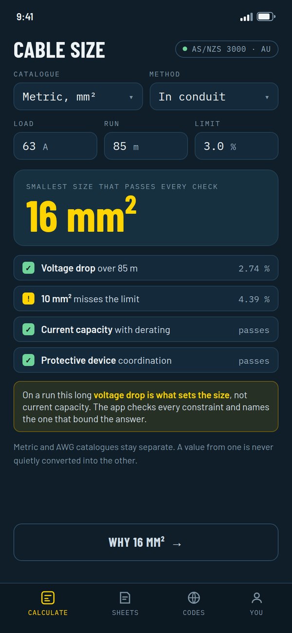
The app works through all of it at once and tells you which check decided the size. See the app.
More free calculators
Voltage drop calculator →
Single phase, three phase and DC, in mm², AWG or kcmil. Shows every step and gives you a sheet to print.
Wire size by voltage drop →
The smallest size that keeps the drop under your limit, plus a list of what it doesn’t check.
Ohm’s law and power →
Volts, amps or ohms from the other two, plus real power for single and three phase.
Conduit fill →
How full your conduit is, for any conduit and any cable, in mm or inches, against the limit from your rules.
Fishtape does the rest
Current capacity with derating, for your code and edition. Short circuit, protective conductor, transformer fault current and conduit fill. Sheets saved by job, and all of it works offline. Leave your email and we’ll send the link.
€1.99 a month, or €29.99 once, for everything. Free for 7 days.
Get it on launch day
We’ll send one email when it’s out. Tell us which code you work to and that pack moves up the list.